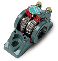
Baldor Electric Company introduces the new Dodge Type EXL tapered roller bearing that provides both misalignment and expansion capability, while maintaining industry standard Type E mounting dimensions. This new design incorporates a cartridge-style inner unit into a split ductile iron housing.
The split-housing design allows the inner unit to swivel freely in the housing allowing up to +/- 4 degrees of static misalignment. Standard Type E products offer virtually no misalignment and are not available in an expansion design. Mounting dimensions are equivalent to any standard Dodge or competitor’s Type E dimensioned product. The totally sealed inner unit incorporates the Dodge XTS triple-lip seal for increased protection in harsh environments. The housing is made from ductile iron for added strength versus cast iron products.
The Type EXL utilizes the new Dodge tapered roller bearings manufactured in Marion, North Carolina. The new bearing design offers a 13% to 14% increase in load ratings over the previous tapered bearing design. The new design is available in both two- and four-bolt pillow blocks and utilizes the same inner unit for both expansion and non-expansion housings. Bore sizes range from 1-3/16 to 5 inches.
The Dodge Type EXL will increase reliability and decrease downtime by offering better sealing, misalignment capability and load ratings versus the competition.
DC motors were first developed in the early 19th century and continue to be used today. Ányos Jedlik is credited as being the first to experiment with DC motors in 1827. William Sturgeon (1832) and Thomas Davenport (1837) are credited with taking Jedlik’s laboratory instrument and trying to commercialize it. It wasn’t until 1871 when Zénobe Gramme’s design of a dynamo was accidentally connected to a second dynamo that was producing a voltage that the DC motor we think of today start to turn and do work.
The DC motor reigned alone in the factory for only 11 years. In 1888, Nicola Tesla stepped into the factory with today’s well known three-phase electric system and the AC induction motor has been taking work away from the DC motor ever since.So, the question remains — why has the DC motor continued to be used from 1888 until today?
A primary reason is the motor’s variable speed characteristic. When the voltage to a DC motor is increased from zero to some base voltage, the motor’s speed increases from zero to a corresponding base speed. An induction motor, on the other hand, always runs at full speed. If a speed other then this is desired, it must be achieved via belts and pulleys, hydraulic pumps and motors, or gear boxes and clutches. These devices provide for rotation at a speed something less (or greater) then the design speed, but adds mechanical complexity.
Click here to continue to read article from Plant Services.
Dodge Group: Baldor has an expanded line of DC Motors
On November 21, 2012, Keyser Elementary’s second and third graders spent their day before Thanksgiving break discovering new and exciting things at Toledo’s very own Imagination Station. As part of a program to sposor schools participation in the education of science, Binkleman assisted by sending both grades to the center for a school trip. We are very excited to be part of such a program and look forward to our growing partnership with both Imagination Station and Keyser Elementary!
Binkelman would like to take this opportunity to sincerely thank our customers and friends for your continued business and support. From all of us here we wish you and your family a wonderul, safe Thanksgiving holiday.
Enjoy the video! Happy Turkey Day!
For most companies that run continuously, shutdowns and outages consume a lion’s share of both the maintenance and capital budgets. By its very nature, the shutdown is fat. The reason for this is the skewed balance between the cost of downtime and the costs of shutdown resources. In some cases the costs of having extra resources (such as extra cranes) are dwarfed by the avoided cost of downtime. Shutdowns are also fat because the attitude is “Get’er done and we’ll worry about the budget when it’s over.” Times have changed. This old approach to shutdowns is taken too far and in itself becomes a fat. It is certainly a fat approach now when times are tough and prices and demand soften. The fact that the downtime is more expensive than resources under any economic condition doesn’t justify the waste of resources.
Discoverables are a key
source of fat. Discoverables are
jobs that are “discovered” after
the shutdown starts (when you
start opening things up.)
Bad meetings are fat.
Use project management
software.
85% of the planning and
scheduling work is done before
the shutdown begins.
Keep an eye on over-
ordering of materials and return
unused inventory as soon as you
know you won’t use it.
Note explicitly whether
there are enough supplies
for the entire shutdown (the
planner should put their hands
on these items and not accept
the computer’s inventory level).
Keep an eye on excessive
numbers of rented cranes,
welding units, generators, compressors, tanks, scaffolding
and other equipment.
Be on the lookout for
situations where resources are
being paid for but are not being
used.
Validate the work list and
remove duplications.
Settle claims with any
contractors promptly to avoid
additional fees and penalties.
The Dodge gear reducer product line offers a full line of modular gear drives engineered for flexibility, greater torque density in a compact housing configuration, and increased horsepower capability from 0.25 to 73.76 hp (0.18 to 55 kW). The Quantis family of products offers the customer three types of gear reducers: In-Line Helical (ILH), Right-Angle Helical Bevel (RHB) and Motorized Shaft Mount (MSM). All three types of reducers are dimensionally interchangeable with major global competitors.
We Can Build A Dodge Gear Reducer For You
Binkelman is authorized to assemble Quantis ILH and RHB in five sizes
(38 through 108). For ILH, two input configurations including c-face clamp collar motor adapters for input motor flexibility and separate inputs for v-belt mounting are available.
RHB input configuration includes c-face clamp collar, and output
configurations of solid, straight hollow and taper shafts.
Factory trained, expert technicians and mechanics
ISO certified and warranted by DODGE
Assembled to order ILH & RHB configurations
Quick delivery response – same day, 24 or 48 hour deliveries can be arranged if required.
Dedicated support staff that’s experienced and knowledgeable about the QUANTIS ILH & RHB product
For more information on DODGE QUANTIS gear reducer solutions click here.
Hydraulic hose provides a basic means for transporting fluid from one component to another, and at the same time it supplies an inherent versatility to designers.
To say that hose is an important part of a hydraulic system is a huge understatement. The flexibility of hose enables components to be positioned in the most efficient or convenient places, because the hose has the ability to bend around corners, through tight spaces, or across long distances.
Yet these days, there seems to be as many different types of hose as there are telephone long-distance carriers. How does a designer tell one from the other? Isn’t there an easy way to choose or compare hoses?
The SAE Standards
SAE answers those questions with its J517 hydraulic hose standard. This hose standard serves as the most popular benchmark in the realm of industrial hydraulics today. More specifically, J517 is a set of guidelines that applies to the current SAE 100R series of hoses. Currently, 16 such hose styles exist, and they are designated as 100R1 through 100R16 (see descriptions, pages A105 and 106). Each of the styles must meet a set of dimensional and performance characteristics as set forth by SAE. However, SAE issues no approval source lists, certification, or letters of approval-conformance to these standards by manufacturers is strictly voluntary. In short, the standards only assure a similarity of products among different manufacturers.
Hydraulic Hose Construction
Modern hydraulic hose typically consists of at least three parts: an inner tube that carries the fluid, a reinforcement layer, and a protective outer layer.
The inner tube must have some flexibility and needs to be compatible with the type of fluid it will carry. Commonly used compounds include synthetic rubber, thermoplastics, and PTFE, sometimes called Teflon. The reinforcement layer consists of one or more sheaths of braided wire, spiral-wound wire, or textile yarn. The outer layer is often weather-, oil-, or abrasion-resistant, depending upon the type of environment the hose is designed for.
Not surprisingly, hydraulic hoses have a finite life. Proper sizing and use of the correct type of hose will certainly extend the life of a hose assembly, but there are many different factors that affect a hose’s lifespan. SAE identifies some of the worst offenses as:
•flexing the hose to less than the specified minimum bend radius
•twisting, pulling, kinking, crushing, or abrading the hose
•operating the hydraulic system above maximum or below minimum temperature
•exposing the hose to rapid or transient rises (surges) in pressure above the maximum operating pressure, and
•intermixing hose, fittings, or assembly equipment not recommended as compatible by the manufacturer or not following the manufacturer’s instructions for fabricating hose assemblies.
Selecting the Proper Hose
Here are seven recommended steps the system designer should follow during the hose and coupling selection process. To help determine the proper hose for an application, use the acronym STAMPED – from Size, Temperature, Application, Materials, Pressure, Ends, and Delivery. Here is what to consider in each area:
Size – In order to select the proper hose size for replacement, it is important to measure the inside and outside hose diameters exactly using a precision-engineered caliper, as well as the length of the hose. Hose OD is particularly important when hose-support clamps are used or when hoses are routed through bulkheads. Check individual hose specification tables for ODs in suppliers’ catalogs. When replacing a hose assembly, always cut the new hose the same length as the one being removed. Moving components of the equipment may pinch or even sever too long a hose. If the replacement hose is too short, pressure may cause the hose to contract and be stretched, leading to reduced service life. Changes in hose length when pressurized range between +2% to 4% while hydraulic mechanisms are in operation. Allow for possible shortening of the hose during operation by making the hose lengths slightly longer than the actual distance between the two connections.
Temperature – All hoses are rated with a maximum working temperature ranging from 200° to 300° F based on the fluid temperature. Exposure to continuous high temperatures can lead to hoses losing their flexibility. Failure to use hydraulic oil with the proper viscosity to hold up under high temperatures can accelerate this problem. Always follow the hose manufacturer’s recommendations. Exceeding these temperature recommendations can reduce hose life by as much as 80%. Depending on materials used, acceptable temperatures may range from -65° F (Hytrel and winterized rubber compounds) to 400° F (PTFE). External temperatures become a factor when hoses are exposed to a turbo manifold or some other heat source. When hoses are exposed to high external and internal temperatures concurrently, there will be a considerable reduction in hose service life. Insulating sleeves can help protect hose from hot equipment parts and other high temperature sources that are potentially hazardous. In these situations, an additional barrier is usually required to shield hydraulic fluid from a potential source of ignition.
Application – Will the selected hose meet bend radius requirements? This refers to the minimum bend radius (usually in inches) that a hydraulic hose must meet. Exceeding this bend radius (using a radius smaller than recommended) is likely to injure the hose reinforcement and reduce hose life. Route high-pressure hydraulic lines parallel to machine contours whenever possible. This practice can help save money by reducing line lengths and minimizing the number of hard-angle, flow-restricting bends. Such routing also can protect lines from external damage and promote easier servicing.
Materials – It is mandatory to consult a compatibility chart to check that the tube compound is compatible with the fluid used in the system. Elevated temperature, fluid contamination, and concentration will affect the chemical compatibility of the tube and fluid. Most hydraulic hoses are compatible with petroleum-based oils. Note that new readily biodegradeable or green fluids may present a problem for some hoses.
Pressure capabilities – Hose working pressure must always be chosen so that it is greater than or equal to the maximum system pressure, including pressure spikes. Pressure spikes greater than the published working pressure will significantly shorten hose life.
Hose ends – The coupling-to-hose mechanical interface must be compatible with the hose selected. The proper mating thread end must be chosen so that connection of the mating components will result in leak-free sealing. There are two general categories of couplings to connect most types of hose: the permanent type (used primarily by equipment manufacturers, large-scale rebuilders, and maintenance shops) and the field-attachable type. Permanently attached couplings are cold-formed onto the hose with powered machinery. They are available for most rubber and thermoplastic hoses and offer a wide range of dependable connections at low cost. Assemblies made in the field with portable machines are relatively simple; these machines are economical and easy to operate. In most cases, it is not necessary to skive the cover. These couplings are less complicated to install than other types. Field-attachable couplings are classified as screw-together and clamp-type. The screw-together coupling attaches to the hose by turning the outer coupling shell over the outside diameter of the hose. The coupling insert is then screwed into the coupling shell. A clamp-type coupling has a 2-piece outer shell that clamps onto the hose OD with either two or four bolts and nuts. In either case, the coupling has limited potential for reuse because the threads distort during attachment. To ensure the correct-size coupling is used when replacing an assembly, the number of threads per inch and thread diameter of the original coupling must be determined. Thread pitch gages are available for identifying the number of threads per inch. A caliper can measure both inside and outside dimensions of the threads. ODs are measured on male couplings, while IDs are measured on female couplings. In most situations, the only differences between an SAE coupling and an imported coupling are the thread configuration and the seat angle. International thread ends can be metric, measured in mm, but also include BSP (British Standard Pipe) threads, which are measured in inches. Knowing the country of origin provides a clue as to what type of thread end is used. DIN (Deutsche Industrial Norme) fittings began in Germany and now are found throughout Europe, while BSP is found on British equipment. Japanese Komatsu machinery uses Komatsu fittings with metric threads, while other Japanese equipment most likely uses JIS (Japanese Industrial StandardBSP threads), or, in some cases, BSP with straight or tapered threads.
Three determinations are required to identify these couplings correctly:
type of seat – inverted (BSPP & DIN), regular (JIS & Komatsu) or flat (flange, flat-face)
seat angle – 30° (JIS, BSP, DIN and Komatsu) or 12° (DIN), and
type of threads – metric (DIN or Komatsu), BSP (BSPP, BSPT or JIS), or tapered (BSPT or JIS Tapered)
SAE standards relating to hydraulic/pneumatic fittings and assemblies specifically designed to eliminate leakage include:
J514 – straight thread ports/fittings
J518c – 4-bolt flange ports/fittings, and
XJ1453 – the number provisionally assigned to O-ring face seal fittings.
Delivery – How available is the product? Is it unique? How soon can it be delivered to the distributor or end user? It may be preferable to consider several options to maximize flexibility and avoid the delays that can result from relying on components that are unavailable or in short supply.
This article was published in the Hydraulic & Pneumatics Magazine. The entire article lists the SAE Hose Specs in detail and is a great reference when specifying hydraulic hose.
Introducing Eaton’s LifeSense™ a patented hydraulic hose condition monitoring technology. LifeSense™ monitors the health of hydraulic hose assemblies. As the hose assembly approaches the end of its useful life, LifeSense™ detects events occurring within the hose that have been shown to lead to failure and notifies the designated individual that the hose needs to be replaced. This notification is provided with enough time to replace the hose during planned maintenance prior to failure thus saving downtime, clean-up costs, environmental damage and potential injury.
Benefits
Provides more than 50% more hose life
Increases reliability – detects and warns of impending failure
Improves maintenance/operations efficiency – automates inspections, ongoing and real-time monitoring
Protects the environment – mitigates potential hazards
Sudden hose failure has been a major potential problem for fluid power applications since hydraulic hose was first introduced decades ago. Sudden failures can lead to safety issues, environmental concerns and downtime that in extreme cases, such as offshore oil rigs, have been estimated to cost as much as $500,000 a day. Click to finish article featured in Design News magazine.
Learn more with video explaning this revolutionary technology.
Mine Expo 2012 is this week, so for those of you that didn’t make it out to Vegas here are some products that can help increase your bottom line.
Conquest XP: ContiTech Engineered Products
ConquestXP™ primary crusher belt has the power to keep your bottom line on its shoulders. Backed by the power of Fortress™ Technology, an innovation in rubber compounding and reinforcement technology, ConquestXP™ is built to excel in impact and puncture resistance. Including one-ply 330, one-ply 440, two-ply 660 and two-ply 880, and available with ContiTech Engineered Products compounds like Defender®, Stacker®, Survivor® and Global X®, this belt is ready for anything you can throw at it. When good just isn’t good enough, start a Conquest.
Retro Rolls: PPI- Precision Pulley and Idler
PPI Retro Rolls allow you to use our proven idler rolls in other manufacturers frames. You get the durability and low maintenance that PPI is known for without having to replace existing frames. Available in CEMA B, C, D, and E Series Rolls. A solution for reduced inventory, labor and downtime.
Belt Cleaners and Plows: Flexco
Belt cleaning is necessary to optimize the performance of your conveyor system. Clean belts will last about 150% longer and require 50% less maintenance, helping to reduce costs and downtime for repairs or maintenance for the entire system.
Mine Duty Extra (MDX) Conveyor Pulleys: Dodge
Drum Pulleys: Standard, stock mine duty drum pulley assemblies that fit CEMA dimensions and exceed the CEMA application standards by two to five times depending upon pulley size. One piece integral hubs that eliminate welded hub heat affected zones (HAZ). HE (High Endurance) 14-degree taper bushings with the lowest bellows installation stress of any taper bushing shaft mounting system for two hub pulley applications. Full 360-degree fillet welding of internal center discs.
Wing Pulleys: Extremely heavy, strong mine duty wing pulley assemblies that fit CEMA dimensions and exceed the CEMA application standards by 2 to 5 times depending upon pulley size. One piece integral hubs that eliminate welded hub heat affected zones (HAZ). HE (High Endurance) 14-degree taper bushings with the lowest installation bellows stress of any taper bushing shaft mounting system for 2 hub pulley applications. Rugged wing-on-drum construction incorporating 2″ x 3/4″ thick contact bars, 3/8″ thick wings and 3/8″ thick spacers.
Quarry Duty Motors: Toshiba
Toshiba’s definite purpose XT, totally enclosed fan cooled, high efficiency, Quarry Duty motor series has a proven track record of exceeding the extreme demands in the cement and aggregate industries. Our Quarry Duty motors utilize a totally enclosed fan cooled design and provide exceptional high torque, oversized superior-grade roller bearings, and shafts built with high strength 4142 steel. The roller bearings on the motor’s drive-end allow for heavy radial loads normally associated with belt-driven applications.
Now available in 5mm, 8mm, 14mm and 20mm sizes,* offering greater productivity and efficiency
Sprocket compatibility with the Gates HTD, PowerGrip GT and GT2, Carlisle RPP and RPP Plus and TB Wood’s Synchronous QD
Enhanced Wingprene™ compound affords greater flexibility, less flex fatigue and longer life
Improved tooth facing for greater abrasion resistance than Hi-Performance Pd Plus
100% greater life expectancy than our previous Hi-Performance Positive Drive Plus belt
Industry-compatible nomenclature for easy part number interchange
Completed Line-up – Hawk Pd is now available in all the popular pitches – 5mm, 8mm, 14mm and 20mm – adding to the universal appeal of this premium product.
Compounding / Reinforcement Integration – Hawk Pd is an exceptional example of a molded, high-performance rubber composite, giving end-users the latest drive belt technology from ContiTech.
MRO Replacement – Hawk Pd can be a superior MRO retrofit to many existing drives, giving the end-user potentially longer life without changing drive hardware.
 Baldor Electric Company introduces the new Dodge Type EXL tapered roller bearing that provides both misalignment and expansion capability, while maintaining industry standard Type E mounting dimensions. This new design incorporates a cartridge-style inner unit into a split ductile iron housing.
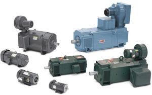 DC motors were first developed in the early 19th century and continue to be used today. Ányos Jedlik is credited as being the first to experiment with DC motors in 1827. William Sturgeon (1832) and Thomas Davenport (1837) are credited with taking Jedlik’s laboratory instrument and trying to commercialize it. It wasn’t until 1871 when Zénobe Gramme’s design of a dynamo was accidentally connected to a second dynamo that was producing a voltage that the DC motor we think of today start to turn and do work.
 On November 21, 2012, Keyser Elementary’s second and third graders spent their day before Thanksgiving break discovering new and exciting things at Toledo’s very own Imagination Station. As part of a program to sposor schools participation in the education of science, Binkleman assisted by sending both grades to the center for a school trip. We are very excited to be part of such a program and look forward to our growing partnership with both Imagination Station and Keyser Elementary!
 Binkelman would like to take this opportunity to sincerely thank our customers and friends for your continued business and support. From all of us here we wish you and your family a wonderul, safe Thanksgiving holiday.
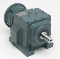 The Dodge gear reducer product line offers a full line of modular gear drives engineered for flexibility, greater torque density in a compact housing configuration, and increased horsepower capability from 0.25 to 73.76 hp (0.18 to 55 kW). The Quantis family of products offers the customer three types of gear reducers: In-Line Helical (ILH), Right-Angle Helical Bevel (RHB) and Motorized Shaft Mount (MSM). All three types of reducers are dimensionally interchangeable with major global competitors.
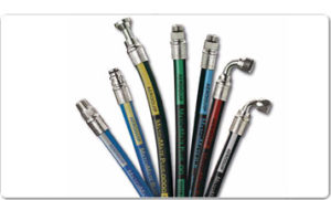 Hydraulic hose provides a basic means for transporting fluid from one component to another, and at the same time it supplies an inherent versatility to designers.
 Introducing Eaton’s LifeSense™ a patented hydraulic hose condition monitoring technology. LifeSense™ monitors the health of hydraulic hose assemblies. As the hose assembly approaches the end of its useful life, LifeSense™ detects events occurring within the hose that have been shown to lead to failure and notifies the designated individual that the hose needs to be replaced. This notification is provided with enough time to replace the hose during planned maintenance prior to failure thus saving downtime, clean-up costs, environmental damage and potential injury.
 Mine Expo 2012 is this week, so for those of you that didn’t make it out to Vegas here are some products that can help increase your bottom line.