When this snow decides to melt and the rains of Spring begin, Binkelman will make sure we have you covered for all of your water suction and discharge hose needs! Binkelman stocks all the products our customers need to keep you dry and out of harms way. So don’t waste anytime and pick up the phone to call us today!
Binkelman Stocks:
1-1/2″ to 6″ ContiTech PVC Spriaflex Discharge Hose
1″ to 6″ ContiTechVersiFlo Water Suction and Discharge Hose
1″ to 3″ ContiTech Spriaflex Clear Green Water Suction and Discharge Hose
All the fittings, strainers, adapters to compliment
Of course, all of our hoses are crimped in-house to the industry standards set forth by North American Hose and Accessory Distributors (NAHAD) Association.
GET READY FOR THE SPRING BY STOCKING UP ON ALL OF YOUR HOSE AND FITTING NEEDS AT BINKELMAN!!
“As TIC continues to grow and evolve, we recognize that our marketing efforts must evolve as well,” said Tatsuo Doko, CEO of TIC. “Today we are proud to announce the launch of our new and improved website.
Aside from a new look and feel, we have made several significant improvements and added key new features summarized below. We hope that you will take this opportunity to become reacquainted with TIC and the many solutions we have available for your business.”
Enhancements to the website include the new and improved search feature which now is site-wide and includes expanded access to content and files. This will save customers time and effort in finding information. TIC recognizes that availability is key to customer service, and with that in mind has highlighted contact information and communication channels on the new website. These highlights include a new FAQ section, question forms on all product pages, dynamic service request forms, and consolidated contact information for all divisions. In addition to the new website, customers now can keep up with the latest TIC news and videos via YouTube and LinkedIn pages.
The recent growth of TIC also is reflected in a number of changes, such as the addition of the Motors and Drives and Power Electronics divisions. These updates include an improved navigation menu, featured products and industries, and online resources like the Motors & Drives matrix. Additional features include links to our Distributor Portal and online promotional store, single sign-on for e-Learning, and one-time registration for downloads.
Binkelman Corporation has been awarded the Partner’s in Education 2012-2013 New Partner of the Year. For the 2012-2013 school year, Binkelman Corporation with Toledo Public Keyser Elementary has contributed over 256 hours of reading and math tutoring with 8 Fourth Grade students, along with a winter apparel drive, painting projects and a field trip to The Imagination Stationfor the 2nd and 3rd grades. On Tuesday, June 11, 2013, Binkelman Corporation was presented this honored award at the Beethoven and Bar-B-Q annual event hosted at the Anderson Complex in Maumee, Ohio. Binkelman program volunteers were treated to a wonderful dinner, a performance by the Toledo Symphony Orchestra and the awards presentation. There were over 150 people in attendance. A special thanks goes to our own insides sales representative, Marcie Kunick and the rest of our volunteers who made this award a reality.
WTOL-TV reporting on Binkelman Corporation’s involvement in the Partners in Education program by mentoring children at Toledo Public School’s Keyser Elementary.
Dixon Frac fittings are sold separately or as a system: the stem (male or female), a heavy duty forged hammer nut and an interlocking ferrule offer customer’s one-piece dependability that is interchangeable with hammer union parts already in service.
FEATURES
interchangeable with current fittings
hammer nut forged to ASTM 105N standards
machined malleable iron stems to ASTM A47; all stems zinc plated
400 PSI working pressure at 70°F
BENEFITS
no leak path as experienced with two-piece threaded systems; phase them into current operation
long lasting and dependable
durable and safe with reliable hose retention
4:1 safety factor (SF)
For more detailed information on this new Dixon One-Piece Frac Fitting click here.
Multiple action shock absorption extends the life of your belt
Available in 2 foot & 5 foot lengths
1/2” thick UHMW for skirt board sealing
Center rolls with tapered discs give twice the impact absorption
Reinforced frames for increased strength
True Impact System (TIS) adds springs for triple action absorption
True Impact System uses extra heavy 1/2” steel plate construction
True Impact System has fold down wings for ease of maintenance
True Impact System includes lift strap to help guide rolls into position
Check out the PPI TIS in action!
Error parsing XSLT file: \xslt\uTube/chromeless.player.xslt
Baldor Electric Company introduces the new Dodge Type EXL tapered roller bearing that provides both misalignment and expansion capability, while maintaining industry standard Type E mounting dimensions. This new design incorporates a cartridge-style inner unit into a split ductile iron housing.
The split-housing design allows the inner unit to swivel freely in the housing allowing up to +/- 4 degrees of static misalignment. Standard Type E products offer virtually no misalignment and are not available in an expansion design. Mounting dimensions are equivalent to any standard Dodge or competitor’s Type E dimensioned product. The totally sealed inner unit incorporates the Dodge XTS triple-lip seal for increased protection in harsh environments. The housing is made from ductile iron for added strength versus cast iron products.
The Type EXL utilizes the new Dodge tapered roller bearings manufactured in Marion, North Carolina. The new bearing design offers a 13% to 14% increase in load ratings over the previous tapered bearing design. The new design is available in both two- and four-bolt pillow blocks and utilizes the same inner unit for both expansion and non-expansion housings. Bore sizes range from 1-3/16 to 5 inches.
The Dodge Type EXL will increase reliability and decrease downtime by offering better sealing, misalignment capability and load ratings versus the competition.
DC motors were first developed in the early 19th century and continue to be used today. Ányos Jedlik is credited as being the first to experiment with DC motors in 1827. William Sturgeon (1832) and Thomas Davenport (1837) are credited with taking Jedlik’s laboratory instrument and trying to commercialize it. It wasn’t until 1871 when Zénobe Gramme’s design of a dynamo was accidentally connected to a second dynamo that was producing a voltage that the DC motor we think of today start to turn and do work.
The DC motor reigned alone in the factory for only 11 years. In 1888, Nicola Tesla stepped into the factory with today’s well known three-phase electric system and the AC induction motor has been taking work away from the DC motor ever since.So, the question remains — why has the DC motor continued to be used from 1888 until today?
A primary reason is the motor’s variable speed characteristic. When the voltage to a DC motor is increased from zero to some base voltage, the motor’s speed increases from zero to a corresponding base speed. An induction motor, on the other hand, always runs at full speed. If a speed other then this is desired, it must be achieved via belts and pulleys, hydraulic pumps and motors, or gear boxes and clutches. These devices provide for rotation at a speed something less (or greater) then the design speed, but adds mechanical complexity.
Click here to continue to read article from Plant Services.
Dodge Group: Baldor has an expanded line of DC Motors
On November 21, 2012, Keyser Elementary’s second and third graders spent their day before Thanksgiving break discovering new and exciting things at Toledo’s very own Imagination Station. As part of a program to sposor schools participation in the education of science, Binkleman assisted by sending both grades to the center for a school trip. We are very excited to be part of such a program and look forward to our growing partnership with both Imagination Station and Keyser Elementary!
Binkelman would like to take this opportunity to sincerely thank our customers and friends for your continued business and support. From all of us here we wish you and your family a wonderul, safe Thanksgiving holiday.
 When this snow decides to melt and the rains of Spring begin, Binkelman will make sure we have you covered for all of your water suction and discharge hose needs! Binkelman stocks all the products our customers need to keep you dry and out of harms way. So don’t waste anytime and pick up the phone to call us today!
 Binkelman Corporation has been awarded the Partner’s in Education 2012-2013 New Partner of the Year. For the 2012-2013 school year, Binkelman Corporation with Toledo Public Keyser Elementary has contributed over 256 hours of reading and math tutoring with 8 Fourth Grade students, along with a winter apparel drive, painting projects and a field trip to The Imagination Stationfor the 2nd and 3rd grades. On Tuesday, June 11, 2013, Binkelman Corporation was presented this honored award at the Beethoven and Bar-B-Q annual event hosted at the Anderson Complex in Maumee, Ohio. Binkelman program volunteers were treated to a wonderful dinner, a performance by the Toledo Symphony Orchestra and the awards presentation. There were over 150 people in attendance. A special thanks goes to our own insides sales representative, Marcie Kunick and the rest of our volunteers who made this award a reality.
 Dixon Frac fittings are sold separately or as a system: the stem (male or female), a heavy duty forged hammer nut and an interlocking ferrule offer customer’s one-piece dependability that is interchangeable with hammer union parts already in service.
 Multiple action shock absorption extends the life of your belt
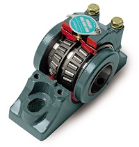 Baldor Electric Company introduces the new Dodge Type EXL tapered roller bearing that provides both misalignment and expansion capability, while maintaining industry standard Type E mounting dimensions. This new design incorporates a cartridge-style inner unit into a split ductile iron housing.
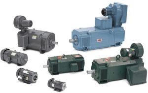 DC motors were first developed in the early 19th century and continue to be used today. Ányos Jedlik is credited as being the first to experiment with DC motors in 1827. William Sturgeon (1832) and Thomas Davenport (1837) are credited with taking Jedlik’s laboratory instrument and trying to commercialize it. It wasn’t until 1871 when Zénobe Gramme’s design of a dynamo was accidentally connected to a second dynamo that was producing a voltage that the DC motor we think of today start to turn and do work.
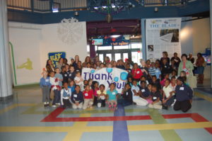 On November 21, 2012, Keyser Elementary’s second and third graders spent their day before Thanksgiving break discovering new and exciting things at Toledo’s very own Imagination Station. As part of a program to sposor schools participation in the education of science, Binkleman assisted by sending both grades to the center for a school trip. We are very excited to be part of such a program and look forward to our growing partnership with both Imagination Station and Keyser Elementary!
 Binkelman would like to take this opportunity to sincerely thank our customers and friends for your continued business and support. From all of us here we wish you and your family a wonderul, safe Thanksgiving holiday.