Properly installing large bore roller bearings is essential in achieving the maximum life of a mounted bearing. It’s estimated that the second most common cause of failure of large bore bearings is improper mounting techniques. Failure can come in the form of shaft-attachment loss, excess vibration and elevated bearing temperatures. Following proper mounting techniques will ensure that the bearing is mounted correctly, and that the maximum life of the bearing will be realized.
There are many different methods of mounting large bore bearings. Common methods include manual assembly, heat shrink, jackscrews, oil injection and hydraulics. The most common is the manual method, which incorporates the use of a hammer and drift, or spanner wrench.
The manual approach involves a bearing, plus a sleeve, nut and washer. The adapter sleeve would be slid over the shaft, and the bearing over the adapter sleeve. The nut would be screwed onto the adapter sleeve, which then forces the bearing up the tapered OD of the sleeve. In turn, the movement of the bearing up the tapered OD of the sleeve would reduce the clearance in the bearing. This provides a press fit to the shaft.
Shim stock is used during this mounting process to measure the amount of radial clearance removed from the bearing. The shim stock is inserted between the roller and outer ring to determine the clearance reduction. When applying this method, the user tightens the nut, checks the clearance reduction, continues to tighten the nut, and measures the clearance reduction until the proper amount of clearance has been removed.
This method has always been suspect, as human error influences the measured values. It’s also very time-consuming, requires extreme physical effort, involves potential safety hazards, and in the end, leads to a questionably mounted bearing.
A solution to this problem is to use hydraulics to mount the bearing. The use of hydraulics dramatically decreases mounting time, eliminates much of the manual effort required, reduces the potential for injuries and ensures a proper press fit between the shaft, adapter and bearing. When mounting a bearing using hydraulics, the standard nut is temporarily replaced with a hydraulic nut.
The hydraulic nut consists of two pieces: the nut and a piston. In this scenario the hydraulic nut is screwed onto the tapered adapter sleeve. Fluid is then pumped into the nut, which causes the piston to extend. The piston comes into contact with the bearing inner ring and pushes it up the tapered adapter sleeve to the starting position. The starting position is considered the point at which the clearance between the shaft, adapter sleeve and bearing bore has been reduced to zero, and the bearing is snug to the shaft.
The next step is to place a measuring device onto the bearing inner ring or face of the piston to measure axial displacement. The measuring device can be as simple as a magnetic-base indicator or a displacement gauge. Continuing to supply hydraulic pressure to the nut will further displace the piston until the final position is obtained. At this point, the hydraulic nut would be removed and replaced by the standard nut.
The hydraulic nut supplier and bearing manufacturer supply the starting position pressure and required final displacement values. Applying hydraulic pressure to set the bearing (and measure axial movement of the bearing to remove the required clearance) replaces the use of shim stock. This provides for a consistently and properly mounted bearing.
Dismounting the bearing can also be a very tedious and time-consuming process, especially if the bearing was mounted without a predetermined method to dismount the bearing. There are several methods of removing bearings, including a manual method, the use of oil injection or a hydraulic dismount nut.
Manually dismounting the bearing usually consists of torching the bearing from the shaft, which destroys the bearing and can damage the shaft. This is also a time-consuming and costly method, especially if the bearing had not failed, but just needed to be re-positioned.
The use of oil injection requires that the shaft, or a special adapter sleeve, contain a hydraulic port plus blind circumferential grooves, which allows hydraulic fluid to be pumped in between the bearing ID and the shaft or adapter OD. While this method will not cause damage to the bearing or the shaft, the hydraulic oil that filled the grooves spills out when the bearing suddenly becomes dismounted. The biggest disadvantage to this method, however, is the high cost of the specially machined adapter sleeve or shaft.
Recognizing the benefits of incorporating hydraulics to mount and dismount bearings, mounted-bearing manufacturers are now supplying products that include pre-assembled hydraulic mount and dismount nuts. Unlike conventional hydraulic nuts, which are separated from the bearings after assembly, the hydraulic nuts used in these new products are an integral part of the bearing assembly and stay with the bearing for the entirety of its life.
The use of the hydraulic dismount nut will remove the bearing from the shaft quickly and easily, without damage to either. Basically, a hydraulic dismount nut functions in the same manner as a hydraulic mount nut. Hydraulic fluid is supplied through the nut and to the piston, which causes the piston to extend and come into contact with the inner ring. Increasing the hydraulic pressure will force the bearing down the tapered adapter sleeve until the bearing is dismounted.
Correctly mounting large bore roller bearings is a critical step to achieving optimum bearing performance and maximum bearing life. By selecting a bearing with a hydraulic system already built in the product, you will reduce mounting and dismounting time, eliminate bearing and shaft damage, and most importantly, end up with a properly mounted bearing.
Greg Hewitt is a Dodge Roller Bearing Development Engineer with Baldor Electric Company. For more information, visitwww.baldor.com.
This article is from the Plant Engineering Magazine link to it by clicking here.
On September 11, 2012, Binkelman Corporation participated in the United Way Week of Caring. Companies all over our community stepped up to make a difference by participating in a variety of community projects. Binkelman chose to re-create a US Map on the playground of neighborhood Keyser Elementary, servicing K-8 grades. Our employees spent a wonderful morning and afternoon creating this lasting, fun, educational piece for the students at Keyser. The enthusiasm shown from the students, teachers and administration was heartwarming and appreciated. Thank you to all the volunteers for the hard work put forth today.
Introducing Baldor Electric Company’s new manufacturing plant in Shelby, North Carolina. With a significant investment from Dodge, this 259,000 square foot facility, which began producing DC motors in June of 2012, is the new home for Dodge’s DMI DC product line and will serve as the global center of excellence for DC motor production.
The original NEMA Premium labeling scheme was designed to simplify the identification and application of NEMA Premium efficient motors by end users and original equipment manufacturers (OEMs). Since its inception, the NEMA Premium mark has gained wide acceptance with motor buyers, utilities, and other specifying organizations. The recognition of NEMA Premium has expanded from the United States to many countries around the globe. NEMA standards include efficiency levels for 60Hz as well as 50 Hz operation.
The National Electrical Manufacturers Association has made significant changes to motor efficiency compliance verification requirements for NEMA Premium licensees.
Motor manufacturers that license NEMA Premium agree that the license is granted on the express condition that the licensee will comply with the NEMA Premium Efficiency Electric Motor Program guidelines which include how to use the NEMA Premium mark along with guidelines of the efficiency verification program. The licensee must agree to follow the guidelines or be subject to termination of the license and the loss of use of the NEMA Premium mark.
NEMA Premium Efficiency Specifications are the energy efficiency levels at which electric motors can qualify for the NEMA Premium designation and are consistent with NEMA MG1 table 12-12. These levels are subject to future review and NEMA expressly reserves the right to maintain or change these levels at any time, consistent with NEMA’s Standardization Policies and Procedures, to maintain the viability and credibility of the NEMA Premium Efficiency Electric Motor Program and its goals. If the efficiency levels are changed at any time by NEMA, the licensee will have 180 days to revise his product to conform to the revised specifications of the NEMA Premium Efficiency Electric Motor Program.
NEMA Premium what does it mean?? Take a look at the below video to answer…
Combustible dusts, according to OSHA, are any combustible solid material composed to distinct particles or pieces, regardless of shape, size or chemical composition that presents a fire or deflagration (exposion) hazard when suspended in air. The National Fire Protection Assoc (NFPA) states that any material that will burn in air as a solid can be explosive in a finely-divided form, and any industrial process that reduces materials into small particles presents a potential for a serious fire or explosion. Facilities that manufacture powders, as well as, those that incidentally generate them through the handling and processing of solid materials are subject to the combustible dust hazard. These materials such as, various metals, wood, plastic, rubber, coal, flour, sugar, and paper. Below are several links that discuss the potential hazards, and prevention of dust explosions.
Sustainable Plant magazine’s June 2012 edition features an in-depth article about the danger of combustible dust.
Get started with Dodge for your variable speed drive application needs using the drives for industry and application guide. Click here for a link to the information for all the drive solutions for your industry. For inquiries regarding drive specification, troubleshooting, or related topics, contact Binkelman’s Kevin Grady at kevin.grady@binkelman.local or 419.537.9333.
The new all-compatible drives portfolio
Aside from all the proper adjustments and operating parameters required to gain the most in screening efficiency, the need for good preventive maintenance practices is a must for longer lasting screens and reliable performance. “Above all, be proactive,” says Deister Machine Co. Service Manager Scott Murphy, an industry veteran with more than 25 years of experience. “Develop a keen focus in forecasting, and then fixing, each factor that could cause potential problems. And take the time to do maintenance the right way — before, rather than after, component failures occur.” Murphy shares the following tips for superior screen maintenance.
Establish an oil sampling program.
Employ recommended lubrication practices.
Maintain proper belt tension.
Prevent material buildup.
Maintain proper screen media support and tensioning.
Binkelman has decades of aggregate industry experience under our “belt”. Call us at 800.863.4673 or click here to contact us for your the MRO needs in your facility.
A big step toward success is choosing the proper lubricant from one of two basic types: mineral-based or synthetic (with the most common synthetic types being hydrocarbon polyalphaolefins [PAOs] and polyalkylene glycols [PAGs]). That choice should be predicated on a product’s characteristics—i.e., viscosity, viscosity index, pour point and additive package.
Conversely, choosing and/or using the wrong product, wrong viscosity, wrong additives, etc., are steps toward improper lubrication. Likewise, not maintaining the correct oil-fill level, operating the gearbox with dirty or contaminated oil and other poor lube practices also can be the kiss of death for your equipment.
Lubricant function in gear reducers
In all speed reducers or gear drives, friction is created between internal moving components. The primary function of the lubricant is to minimize the friction caused by the sliding and rolling action of the gears and bearings and to dissipate heat by providing a thin layer of oil between moving components. With a typical thickness of just 0.00005 of an inch, this layer of oil, known as elastohydrodynamic (EHD) film, separates the mating surfaces of components, preventing metal-to-metal contact and minimizing wear. If the EHD film is insufficient for the transmitted load, metal-to-metal contact of the mating surfaces occurs and causes pitting of gear teeth. No EHD film—or an insufficient amount of it—can also cause scuffing of the gear teeth and leads to bearing and gear failure.
Pumps have historically been a backbone of many applications, including commercial buildings, municipal water and wastewater management, irrigation and agriculture; and are certainly key contributors in industrial systems found in chemical, oil and gas, and pulp and paper industries. Pumping systems account for nearly 25 percent of the energy consumed by electric motors, and for 20 to 60 percent of the total electrical energy usage in many industrial, water and wastewater treatment facilities. Optimizing these processes presents extensive potential savings opportunities, which far exceed more commonplace activity such as motor maintenance/optimization and fan/compressor system upgrades.
While pumps continue to perform the tasks for which they were designed – movement of liquids/solids – there are several trends impacting the future of pumps and pump systems. Historically, pumps have been supplied as part of larger systems and were frequently misapplied, improperly sized, and generally left to be standalone components in larger systems. Many trends in various industrial markets have increased the visibility of pumping, and ultimately the “pump system” as a key component. Key trends include:
The Toshiba P9 low voltage adjustable speed drive is a revolution in pump control. By incorporating Toshiba’s proprietary, ground-breaking Virtual Linear Pump (VLP) Technology, the P9 directly, precisely, and linearly controls pressure, temperature, or flow. The P9 eliminates many obstacles users thought were an integral part of pump control and sets a new standard in ingenuity, performance, and ease-of-use for the pump industry. The below video gives an overview of the features of the P9.
Hydraulic hoses are literally the life lines of most construction equipment. Nothing can grind productivity to a halt faster than a ruptured hose. A little time invested up front to monitor the condition of the hydraulic hoses and fittings can dramatically reduce expensive failures in the field. “The potential cost of hose failure in terms of lost production, environmental impacts and possible injury to operators and others argues strongly in favor of replacing hoses on a time-based schedule, periodic visual inspection or some combination of the two,” says Douglas Jahnke, marketing manager, Eaton’s Hydraulics Group. “Hose replacement while equipment is already ‘out of service’ as part of a planned preventive maintenance schedule can prevent critical downtime and expense.“As a general rule, hoses should be replaced as part of a preventive maintenance(PM)program, especially in critical applications,” agrees Tim Deans, Gates Global Hydraulic Systems engineer. “Consider that hose shelf life is similar to automobile tires. After four to six years,the rubber begins to break down and you can expect to see visual cracking and weeping around the couplings.”

 The original NEMA Premium labeling scheme was designed to simplify the identification and application of NEMA Premium efficient motors by end users and original equipment manufacturers (OEMs). Since its inception, the NEMA Premium mark has gained wide acceptance with motor buyers, utilities, and other specifying organizations. The recognition of NEMA Premium has expanded from the United States to many countries around the globe. NEMA standards include efficiency levels for 60Hz as well as 50 Hz operation.
 Aside from all the proper adjustments and operating parameters required to gain the most in screening efficiency, the need for good preventive maintenance practices is a must for longer lasting screens and reliable performance. “Above all, be proactive,” says Deister Machine Co. Service Manager Scott Murphy, an industry veteran with more than 25 years of experience. “Develop a keen focus in forecasting, and then fixing, each factor that could cause potential problems. And take the time to do maintenance the right way — before, rather than after, component failures occur.” Murphy shares the following tips for superior screen maintenance.
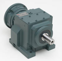 A big step toward success is choosing the proper lubricant from one of two basic types: mineral-based or synthetic (with the most common synthetic types being hydrocarbon polyalphaolefins [PAOs] and polyalkylene glycols [PAGs]). That choice should be predicated on a product’s characteristics—i.e., viscosity, viscosity index, pour point and additive package.
 Pumps have historically been a backbone of many applications, including commercial buildings, municipal water and wastewater management, irrigation and agriculture; and are certainly key contributors in industrial systems found in chemical, oil and gas, and pulp and paper industries. Pumping systems account for nearly 25 percent of the energy consumed by electric motors, and for 20 to 60 percent of the total electrical energy usage in many industrial, water and wastewater treatment facilities. Optimizing these processes presents extensive potential savings opportunities, which far exceed more commonplace activity such as motor maintenance/optimization and fan/compressor system upgrades.
 Hydraulic hoses are literally the life lines of most construction equipment. Nothing can grind productivity to a halt faster than a ruptured hose. A little time invested up front to monitor the condition of the hydraulic hoses and fittings can dramatically reduce expensive failures in the field. “The potential cost of hose failure in terms of lost production, environmental impacts and possible injury to operators and others argues strongly in favor of replacing hoses on a time-based schedule, periodic visual inspection or some combination of the two,” says Douglas Jahnke, marketing manager, Eaton’s Hydraulics Group. “Hose replacement while equipment is already ‘out of service’ as part of a planned preventive maintenance schedule can prevent critical downtime and expense.“As a general rule, hoses should be replaced as part of a preventive maintenance(PM)program, especially in critical applications,” agrees Tim Deans, Gates Global Hydraulic Systems engineer. “Consider that hose shelf life is similar to automobile tires. After four to six years,the rubber begins to break down and you can expect to see visual cracking and weeping around the couplings.”